Author Archives: admin

H-Brücken und ähnliches für flipdot und VFD Ansteuerung

Sammlung von A/D Wandler etc.

Diverses aus dem Bereich A/D Wandlung

Wandler

Referenzspannungsquellen:

  • http://www.microchip.com/wwwproducts/en/MCP1501 0,1% Referenz mit 1024mV, 1250mV, 1500mV, 2048mV, … Ideal für direkte Messwertausgabe (bei 10 Bit und 1024mV -> 1 Bit=1mV), enthält bereits integrierten OpAmp für den Ausgang (+- 20mA), $0.70

AFE:

GPS / PPS basierter NTP-Server auf Raspberry Pi

Im Netz gibt es mittlerweile viele Anleitung zu NTP über GPS (siehe http://doc.ntp.org/4.2.6/drivers/driver20.html oder http://www.satsignal.eu/ntp/Raspberry-Pi-NTP.html). Aber entweder werden spezielle Receiver verwendet, oder PPS funktioniert nicht. Daher hier die Anleitung für Dummies:

Vorbereitung Empfänger:

Als Empfänger kommt der billigste u-blox7 Empfänger zum Einsatz (z.B. hier: https://www.amazon.de/dp/B015E2XSSO/), der über USB als serielles Gerät die NMEA Daten liefert. Doch wir wollen auch das PPS-Signal! -> Lötkolben

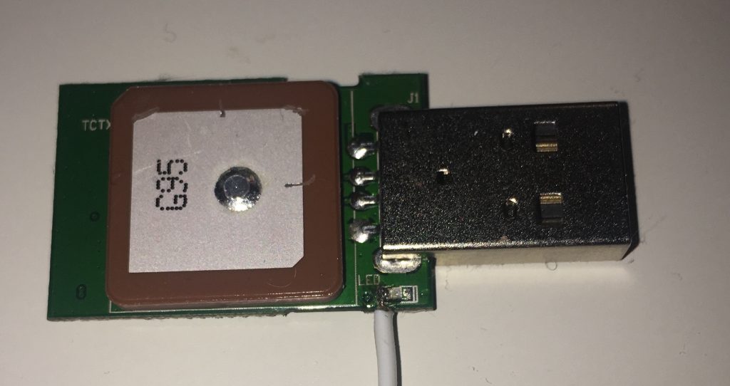
Die LED wird mit dem PPS-Signal des Empfängers betrieben und hat einen Pegel von etwa 2,8V und kann damit direkt an den Raspberry angeschlossen werden (GPIO-18 in unserem Fall).

Raspberry Pi

Kerneleinstellungen:

Laden der folgenden Module (eintragen in /etc/modules):

i2c-dev
pps-gpio

Aktivieren des PPS-GPIO Moduls auf Pin 18 (Eintragen als letzte Zeile in /boot/config.txt):

dtoverlay=pps-gpio,gpiopin=18

Das pps-gpio Modul stellt sicher, dass das PPS Signal ausgewertet werden kann. Zusätzlich wird noch das Paket pps-tools benötigt, das mittels

apt-get install pps-tools

installiert werden kann. Die Änderung wird nach einem Reboot aktiv. Und kann mittels:

pi@raspberrypi:~ $ sudo ppstest /dev/pps0
trying PPS source "/dev/pps0"
found PPS source "/dev/pps0"
ok, found 1 source(s), now start fetching data...
source 0 - assert 1493324550.000003956, sequence: 456311 - clear 0.000000000, sequence: 0
source 0 - assert 1493324551.000001890, sequence: 456312 - clear 0.000000000, sequence: 0
source 0 - assert 1493324552.000001441, sequence: 456313 - clear 0.000000000, sequence: 0

geprüft werden.

NTP compilieren, da raspbian keine PPS Unterstützung mitbringt:

mkdir install
pi@raspberrypi:~ $ cd install
pi@raspberrypi:~/install $ sudo apt-get install libcap-dev
pi@raspberrypi:~/install $ sudo apt-get install libssl-dev
pi@raspberrypi:~/install $ sudo apt-get remove ntp
pi@raspberrypi:~/install $ wget https://www.eecis.udel.edu/~ntp/ntp_spool/ntp4/ntp-4.2/pi@raspberrypi:~/install $ tar xzf ntp-4.2.8p12.tar.gz
pi@raspberrypi:~/install $ apt-get install pps-tools
pi@raspberrypi:~/install $ cd ntp-4.2.8p12/
pi@raspberrypi:~/install/ntp-4.2.8p12 $ ./configure --enable-linuxcaps
pi@raspberrypi:~/install/ntp-4.2.8p12 $ make -j4
pi@raspberrypi:~/install/ntp-4.2.8p12 $ sudo make install && sudo cp /usr/local/bin/ntp* /usr/bin/  && sudo cp /usr/local/sbin/ntp* /usr/sbin/


NTP Konfiguration

In /etc/ntp.conf.dhcp folgendes eintragen:

driftfile /var/lib/ntp/ntp.drift
statsdir /var/log/ntpstats/
statistics loopstats peerstats clockstats

filegen loopstats file loopstats type day enable
filegen peerstats file peerstats type day enable
filegen clockstats file clockstats type day enable

server 0.debian.pool.ntp.org iburst
server 1.debian.pool.ntp.org iburst
server 2.debian.pool.ntp.org iburst
server 3.debian.pool.ntp.org iburst

server 127.127.20.0 minpoll 2 maxpoll 4 prefer # GPSd
fudge 127.127.20.0 flag1 1 refid NMEA
server 127.127.22.0 minpoll 4 maxpoll 4
fudge 127.127.22.0  refid PPS
restrict -4 default kod notrap nomodify nopeer noquery
restrict -6 default kod notrap nomodify nopeer noquery
restrict 127.0.0.1
restrict ::1

Jetzt fehlt “nur” noch die Verbindung des GPS Treibers (127.127.20.0) und PPS Treibers (127.127.22.0) zu unserem GPS Empfänger. Der Treiber 20 bzw. 22 verwendet hardcodiert die Dateien /dev/gpsX und /dev/gpsppsX für die NMEA und PPS Informationen. Ein einfacher Symlink reicht leider nicht, da dieser beim Reboot wieder gelöscht wird. Stattdessen via /etc/udev/rules.d/09.pps.rules automatisch eintragen lassen (siehe Comment from Pete Stephenson on http://www.satsignal.eu/ntp/RaspberryPi-notes.html):

KERNEL=="ttyACM0", SYMLINK+="gps0"
KERNEL=="pps0", OWNER="root", GROUP="tty", MODE="0660", SYMLINK+="gpspps0"

Neustart des ntp-Servers mittels /etc/init.d/ntp restart. Damit die beiden Symlinks auch nach einem Reboot aktiv bleiben, die Anlage der symlinks in die /etc/rc.local eintragen:

ln -s /dev/pps0 /dev/gpspps0
ln -s /dev/ttyACM0 /dev/gps0

Abfrage des Timeservers mittels: ntpq -c peers -c rv :

 remote          refid        st t when poll reach    delay   offset jitter
==============================================================================
oGPS_NMEA(0)     .NMEA.        0 l    -    8   377    0.000   -0.003  0.002
-ntp0.technl.net 80.114.85.144 2 u   47   64   377   48.622   -9.328  2.313
+mail.veland.de  89.238.79.186 3 u   47   64   377   38.701    2.456  3.736
+v6.blazing.de   213.172.96.14 2 u   52   64   377   28.919   -0.301  2.960
+217.79.179.106  212.51.144.44 2 u   57   64   377   31.623   -0.386  2.552
associd=0 status=0415 leap_none, sync_uhf_radio, 1 event, clock_sync,
version="ntpd 4.2.8p10@1.3728-o Sun Apr 16 12:01:26 UTC 2017 (1)",
processor="armv7l", system="Linux/4.4.50-v7+", leap=00, stratum=1,
precision=-19, rootdelay=0.000, rootdisp=1.000, refid=NMEA,
reftime=dcaccfd1.533a3357 Thu, Apr 27 2017 20:15:13.325,
clock=dcaccfd1.9db99523 Thu, Apr 27 2017 20:15:13.616, peer=36778, tc=3,
mintc=3, offset=-0.003099, frequency=-13.013, sys_jitter=0.002371,
clk_jitter=0.002, clk_wander=0.001

Der jitter kann evtl. noch verbessert werden durch die Angabe von nohz=off (http://www.satsignal.eu/ntp/Raspberry-Pi-NTP.html#nohz) und fixe Frequenzen für arm_freq_min und arm_freq_max, aber das muss ich selbst erst noch beobachten.

I2S Mikrofon und PIC32MX170F256 als Alternative zu MSGEQ-7

Als günstige Alternative zu einem MSGEQ-7 (Einzelpreis 5,45€) für ein Graphic Equalizer Display (5-Kanal Lichtorgel) ein kleiner Exkurs in die DSP Welt:

Von Knowles gibt es sehr (sehr) kleine Mikrofone, die direkt das Audio Signal als I2S Datenstrom ausgeben (Einzelpreis 2€).

Dieses wird direkt an den I2S Port des PIC32 (Einzelpreis 4€) angeschlossen und mittels DMA im Hintergrund ausgelesen. Nach jeweils 4096 Samples bei 48 kHz wird der DMA Interrupt ausgelöst (etwa 48 mal pro Sekunde) und die Samples des unbeschalteten Kanals weggeworfen und je zwei aufeinanderfolgende Samples des verbleibenden Kanals gemittelt.

Die so übrig bleibenden 1024 Samples (mit einer Abtastfrequenz von nun 24 kHz) werden dann mittels FFT in den Frequenzraum überführt und auf die 5 Bänder aufgeteilt.

Die Anzeige der Balken erfolgt über eine Matrix aus WS2812 LEDs:

bildschirmfoto-2016-09-23-um-21-14-11

RS485 Interface an einem PIC16F1708

Neues Projekt mit RS-485 Interface: 29 Module mit je 37 LEDs, die über einen Raspberry Pi gesteuert werden sollen.

Problem: der PIC16F1708 ist nicht in der Lage festzustellen, ob noch eine Übertragung via EUSART Modul aktiv ist (Quote: “The TSR register is not mapped in data memory, so it is not available to the user.”). Die Transmitter-Enable Leitung (DE) kann also nicht mit dem letzten gesendeten Bit wieder deaktiviert werden.

Lösung: Beim Senden von jedem Zeichen die DE Leitung auf High setzen (und so den 75176 in Sendemodus bringen), den TMR0 (re-)starten und im Interrupt-Handler von TMR0 dann die DE Leitung wieder auf Low setzen:

void TMR0_CallBack(void) {
  IO_DE_SetLow();
}

void RS485_Put(uint8_t c) {
  IO_DE_SetHigh();
  TMR0_Reload();
  EUSART_Write(c);
}

void RS485_Print(const unsigned char* message) {
  char c; 
  while (c = *message++) {
    RS485_Put(c);
  } 
}

char to_hex(uint8_t v) {
  v = v & 0xf;
  if (v<10) {
    return '0'+v;
  }
  return 'A'-10+v;
}

void RS485_PrintHex8(uint8_t val) {
  RS485_Put(to_hex(val>>4));
  RS485_Put(to_hex(val));
}

void RS485_PrintHex16(uint16_t val) {
  RS485_Put(to_hex(val>>12));
  RS485_Put(to_hex(val>>8));
  RS485_Put(to_hex(val>>4));
  RS485_Put(to_hex(val));
}

void RS485_PrintDecimal(uint16_t val) {
  RS485_Put('0'+ ((val/10000) % 10 ));
  RS485_Put('0'+ ((val/1000) % 10 ));
  RS485_Put('0'+ ((val/100) % 10 ));
  RS485_Put('0'+ ((val/10) % 10 ));
  RS485_Put('0'+ ((val/1) % 10 ));
}

Mailserver mit Postfix, dovecot, spamassassin, opendkim und postgrey unter debian jessy

Der alte Server war dann doch etwas langsam, daher der Umzug auf neue Hardware. Mit dem Umzug galt es auch den bisherigen IMAP Server (cyrus) durch dovecot zu ersetzen. Soweit der Vorsatz, die Umsetzung war dann weitaus schwieriger…

Setup

Neben der Grundfunktionalität (Mails empfangen und senden) sollte der Mailserver wenigstens folgendes können:

  • DKIM zur Authentifizierung
  • SPF
  • Greylisting
  • spamassassin Unterstützung
  • Volltextsuche über IMAP
  • Mehrere virtuelle Domains
  • Weiterleitungen
  • Mehrere Benutzer für IMAP/SMTP
  • TLS Unterstützung

Continue reading

DCF77 Empfang mit Arduino

Da mein DCF-77 Empfänger ab und zu Aussetzer zeigte, funktionierte der Code von http://gonium.net/md/2007/01/06/arduino-dcf77-v02-released/ leider nicht auf Anhieb.

Offenbar war die Flankensteilheit des Ausgangs nicht ausreichend, so dass gerade bei den fallenden Flanken mehrere Interrupts ausgelöst wurden. Daher gibt es jetzt eine Prüfung, ob der Interrupt mindestens 10 ms nach dem letzten eingetreten ist.

/**
 * Arduino DCF77 decoder v0.3
 * Copyright (C) 2006 Mathias Dalheimer (md@gonium.net)
 *           (C) 2010 Wolfgang Jung (w@elektrowolle.de)
 * This program is free software; you can redistribute it and/or modify
 * it under the terms of the GNU General Public License as published by
 * the Free Software Foundation; either version 2 of the License, or
 * any later version.
 * 
 * This program is distributed in the hope that it will be useful,
 * but WITHOUT ANY WARRANTY; without even the implied warranty of
 * MERCHANTABILITY or FITNESS FOR A PARTICULAR PURPOSE.  See the
 * GNU General Public License for more details.
 * 
 * You should have received a copy of the GNU General Public License along
 * with this program; if not, write to the Free Software Foundation, Inc.,
 * 51 Franklin Street, Fifth Floor, Boston, MA 02110-1301 USA.
 */
#include <MsTimer2.h>

/**
 * Where is the DCF receiver connected? Must be attachable to an interrupt
 * (PIN 2 or PIN 3).
 */
#define DCF77PIN 2
/**
 * Where is the LED connected?
 */
#define BLINKPIN 13

/**
 * Turn debugging on or off
 */
#define DCF_DEBUG 1
/**
 * Number of milliseconds to elapse before we assume a "1",
 * if we receive a falling flank before - its a 0.
 */
#define DCF_split_millis 140
/**
 * There is no signal in second 59 - detect the beginning of 
 * a new minute.
 */
#define DCF_sync_millis 1200

/** 
 * Signals shorter than this should be ignored
 */
#define DCF_MAX_JITTER 10

/** 
 * Signals shorter than this should be ignored
 */
#define DCF_SHORT_SIGNAL 50

/**
 * DCF time format struct
 */
struct DCF77Buffer {
  unsigned long long prefix	:21;
  unsigned long long Min	:7;	// minutes
  unsigned long long P1		:1;	// parity minutes
  unsigned long long Hour	:6;	// hours
  unsigned long long P2		:1;	// parity hours
  unsigned long long Day	:6;	// day
  unsigned long long Weekday	:3;	// day of week
  unsigned long long Month	:5;	// month
  unsigned long long Year	:8;	// year (5 -> 2005)
  unsigned long long P3		:1;	// parity
};

struct {
	unsigned char parity_flag	:1;
	unsigned char parity_min	:1;
	unsigned char parity_hour	:1;
	unsigned char parity_date	:1;
} flags;

/**
 * Clock variables 
 */
volatile unsigned char DCFSignalState = 0;  
unsigned char previousSignalState;
int previousFlankTime;
int bufferPosition;
unsigned long long dcf_rx_buffer;

/**
 * time vars: the time is stored here!
 */
volatile unsigned char ss;
volatile unsigned char mm;
volatile unsigned char hh;
volatile unsigned char day;
volatile unsigned char mon;
volatile unsigned int year;
    

/**
 * used in main loop: detect a new second...
 */
unsigned char previousSecond;
    
/**
 * Initialize the DCF77 routines: initialize the variables,
 * configure the interrupt behaviour.
 */
void DCF77Init() {
  previousSignalState=0;
  previousFlankTime=0;
  bufferPosition=0;
  dcf_rx_buffer=0;
  ss=mm=hh=day=mon=year=0;
#ifdef DCF_DEBUG 
  Serial.println("Initializing DCF77 routines");
  Serial.print("Using DCF77 pin #");
  Serial.println(DCF77PIN);
#endif
  pinMode(BLINKPIN, OUTPUT);
  pinMode(DCF77PIN, INPUT);
  
#ifdef DCF_DEBUG
  Serial.println("Initializing timerinterrupt");
#endif
  MsTimer2::set(1000, advanceClock); // every second

#ifdef DCF_DEBUG
  Serial.println("Initializing DCF77 signal listener interrupt");
#endif  
  attachInterrupt(0, int0handler, CHANGE);
}

/**
 * Append a signal to the dcf_rx_buffer. Argument can be 1 or 0. An internal
 * counter shifts the writing position within the buffer. If position > 59,
 * a new minute begins -> time to call finalizeBuffer().
 */
void appendSignal(unsigned char signal) {
#ifdef DCF_DEBUG
  Serial.print(", appending value ");
  Serial.print(signal, DEC);
  Serial.print(" at position ");
  Serial.println(bufferPosition);
#endif
  dcf_rx_buffer = dcf_rx_buffer | ((unsigned long long) signal << bufferPosition);
  // Update the parity bits. First: Reset when minute, hour or date starts.
  if (bufferPosition ==  21 || bufferPosition ==  29 || bufferPosition ==  36) {
	flags.parity_flag = 0;
  }
  // save the parity when the corresponding segment ends
  if (bufferPosition ==  28) {flags.parity_min = flags.parity_flag;};
  if (bufferPosition ==  35) {flags.parity_hour = flags.parity_flag;};
  if (bufferPosition ==  58) {flags.parity_date = flags.parity_flag;};
  // When we received a 1, toggle the parity flag
  if (signal == 1) {
    flags.parity_flag = flags.parity_flag ^ 1;
  }
  bufferPosition++;
  if (bufferPosition > 59) {
    finalizeBuffer();
  }
}

/**
 * Evaluates the information stored in the buffer. This is where the DCF77
 * signal is decoded and the internal clock is updated.
 */
void finalizeBuffer(void) {
  if (bufferPosition == 59) {
#ifdef DCF_DEBUG
    Serial.println("Finalizing Buffer");
#endif
    struct DCF77Buffer *rx_buffer;
    rx_buffer = (struct DCF77Buffer *)(unsigned long long)&dcf_rx_buffer;
    if (flags.parity_min == rx_buffer->P1  &&
        flags.parity_hour == rx_buffer->P2  &&
        flags.parity_date == rx_buffer->P3) 
    { 
#ifdef DCF_DEBUG
      Serial.println("Parity check OK - updating time.");
#endif
      //convert the received bits from BCD
      mm = rx_buffer->Min-((rx_buffer->Min/16)*6);
      hh = rx_buffer->Hour-((rx_buffer->Hour/16)*6);
      day= rx_buffer->Day-((rx_buffer->Day/16)*6); 
      mon= rx_buffer->Month-((rx_buffer->Month/16)*6);
      year= 2000 + rx_buffer->Year-((rx_buffer->Year/16)*6);
      // Start or reset the timer for the seconds
      MsTimer2::start();      
    }
#ifdef DCF_DEBUG
      else {
        Serial.println("Parity check NOK - running on internal clock.");
    }
#endif
  } 
  // reset stuff
  ss = 0;
  bufferPosition = 0;
  dcf_rx_buffer=0;
}

/**
 * Dump the time to the serial line.
 */
void serialDumpTime(void){
#ifdef DCF_DEBUG
  Serial.print("Time: ");
  Serial.print(hh, DEC);
  Serial.print(":");
  Serial.print(mm, DEC);
  Serial.print(":");
  Serial.print(ss, DEC);
  Serial.print(" Date: ");
  Serial.print(day, DEC);
  Serial.print(".");
  Serial.print(mon, DEC);
  Serial.print(".");
  Serial.println(year, DEC);
#endif
}

/**
 * Evaluates the signal as it is received. Decides whether we received
 * a "1" or a "0" based on the 
 */
void scanSignal(void){ 
    digitalWrite(BLINKPIN, DCFSignalState);
    if (DCFSignalState == 1) {
      int thisFlankTime=millis();
      if (thisFlankTime - previousFlankTime > DCF_sync_millis) {
#ifdef DCF_DEBUG
        Serial.println("####");
        Serial.println("#### Begin of new Minute!!!");
        Serial.println("####");
#endif
        finalizeBuffer();
      }
      previousFlankTime=thisFlankTime;
#ifdef DCF_DEBUG
      Serial.print(previousFlankTime);
      Serial.print(": DCF77 Signal detected, ");
#endif
    } 
    else {
      /* or a falling flank */
      int difference=millis() - previousFlankTime;
#ifdef DCF_DEBUG
      Serial.print("duration: ");
      Serial.print(difference);
#endif
      if (difference < DCF_SHORT_SIGNAL) {
        // ignore short signals
      }  else if (difference < DCF_split_millis) {
        appendSignal(0);
      } else {
        appendSignal(1);
      }
    }
}

/**
 * The interrupt routine for counting seconds - increment hh:mm:ss.
 */
void advanceClock() {
    ss++;
    if (ss==60) {
      ss=0;
      mm++;
      if (mm==60) {
        mm=0;
        hh++;
        if (hh==24) 
          hh=0;
      }
    }
}

/**
 * Interrupthandler for INT0 - called when the signal on Pin 2 changes.
 */
void int0handler() {
  int length = millis() - previousFlankTime;
  if (length < DCF_MAX_JITTER) {
    // ignore jitter
    return;
  }
  // check the value again - since it takes some time to
  // activate the interrupt routine, we get a clear signal.
  DCFSignalState = digitalRead(DCF77PIN);
}


/**
 * Standard Arduino methods below.
 */

void setup(void) {
  // We need to start serial here again, 
  // for Arduino 007 (new serial code)
#ifdef DCF_DEBUG
  Serial.begin(9600);
#endif
  DCF77Init();
}


void loop(void) {
  
  if (ss != previousSecond) {
    serialDumpTime();
    previousSecond = ss;
  }
  if (DCFSignalState != previousSignalState) {
    scanSignal();
    previousSignalState = DCFSignalState;
  }
    //delay(20);
}